VE3BYT |
The
Skew-Planar Wheel Antenna - Revisited |
VE3KL |
|
This
is a useful antenna design that has been forgotten for 40 years.
It has a low omnidirectional pattern and is circularly polarized. |
||
| By
Graham
Ide, VE3BYT, with David Conn, VE3KL. ve3byt@rac.ca |
||
| This
article was published in the November/December 2006 issue of TCA, The Canadian Amateur magazine. There is a brief description of the Skew-Planar Wheel Antenna at <www.slvrc.org/902band/skewplanar.htm> with an additional example of the antenna at 2.4 GHz, and a scan of the information from the 1964 ARRL Antenna Book, which shows it used mobile on the 144 MHz band - pages 320, 321. |

|
Interest
in this antenna design arose when the West Carleton Amateur Radio Club
in Ottawa decided to erect a beacon transmitter in the 902-928 MHz band.
Discussion led club members to debate what
characteristics the antenna should have.
It was quickly decided that the antenna must have horizontal
polarization, in keeping with weak-signal conventions.
I voiced the opinion that ideally, the antenna should be
circularly-polarized, so that the beacon signal might be received well
on both vertically and horizontally polarized antennas.
I was immediately delegated to devise, construct and supply such
an antenna for the beacon project.
So much for passive and innocent contributions to the discussion!
The Lindenblad antenna [1] design is familiar to many amateurs.
This antenna has a circularly polarized response with a low
horizontal pattern, so it is useful for satellite passes as the bird
rises or sets near the horizon. An
example of the Lindenblad antenna is illustrated for the 2 Metre band in
the Satellite Experimenters' Handbook published by ARRL.
This particular design uses four folded dipoles fed together
using paralleled 300 ohm twinlead.
Suitable instruments were not readily available for measuring
impedances and for matching at 903 MHz when I was considering antenna
designs, so I could foresee some difficulties with constructing and
matching a Lindenblad for transmitting purposes.
Stuck
with the need to produce or shut up (the latter was not really an
option), I considered the situation for a time.
I remembered seeing information on an antenna design with
circular polarization that was used for mobile work many years ago on
the 2 Metre band. This was
back in the days when such activity was mostly on AM, usually using Halo
antennas on the mobiles. This
antenna, the Skew-Planar Wheel, was described
in QST in November 1963 [2] and is illustrated in the 1964
edition of the ARRL Antenna Book. As
far as I know, it has seldom been referred to since that time.
A search of the Internet did not produce any further examples or
information on it beyond my web page [3].
It appeared that the amateur community had forgotten this
antenna. This is
interesting in itself, because the same amateurs who designed the Big
Wheel Antenna built the Skew-Planar Wheel antenna, Carl Milner, W1FVY,
and Robert Mellen, W1IJD.
The
Big Wheel antenna design [4] is quite widely used today on the 144 and
430 MHz bands. It is
horizontally polarized, so in fixed use it has some gain advantage over
a single circularly polarized antenna in working locally with other
horizontal antennas. However, the Skew Planar is preferable to meet the objectives
for the beacon antenna and for other
applications with its an omnidirectional low angle pattern and
circular polarization – useful both for working repeaters and mobiles,
and for local SSB nets where the other stations are using horizontal
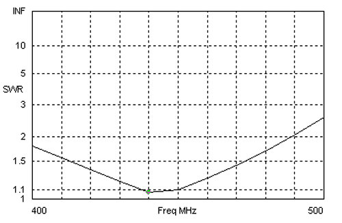
antennas. The
broad frequency response of the Skew-Planar antenna with low SWR is a
big plus.
The Skew-Planar antenna is a bit of a beast for 144 or 222 MHz mobile
operations because of its size at these frequencies, but could be
advantageous for fixed-station use.
Mobile operation on these bands has for many years been almost
exclusively FM, using vertical antennas. First
Experiments
Doug
Leach, VE3XK, and I investigated the beacon antenna using a network analyzer, and it looked pretty good with broad frequency response and a
good match for 50 ohm cable, although the one wavelength-long elements
put the optimum resonant frequency a little high.
The analyser showed that the elements should be somewhat longer
than the one wavelength suggested in the original article on this
antenna.
We were pleased with the apparent performance of the Skew-Planar
antenna. But the question
of its actual characteristics remained. We wanted to verify that the
antenna does in fact produce circular polarization, and to determine its
radiation pattern in the horizontal and vertical planes.
We needed to satisfy ourselves that it was doing what we were
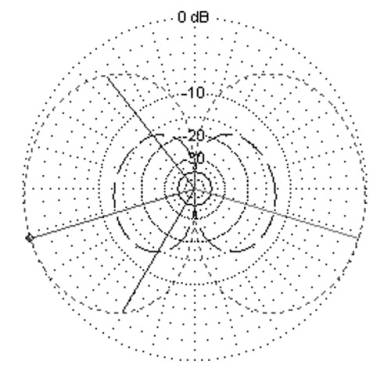
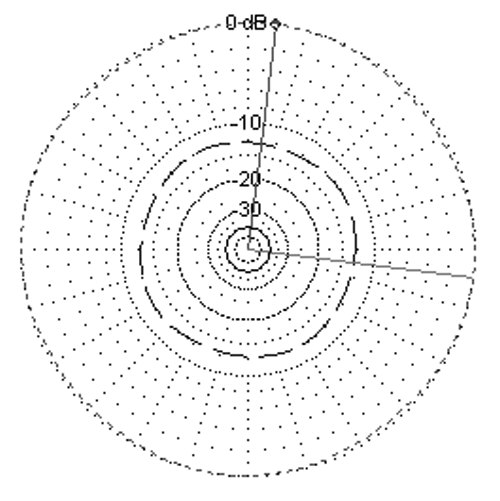
hoping it was. Antenna Simulations David Conn, VE3KL, conducted extensive analyses of the design at various frequencies. David used EZNEC [5] and programming in Visual Basic to determine the complex wire descriptions needed for the skew-Planar antenna. The resulting Elevation plot of the antenna at 440 MHz is shown in Figure 1 and the Azimuth plot in Figure 2. This antenna, designed for right-hand circular polarization, has a left-hand component as well. It responds to and produces left-hand circularly polarized radiation at 13 dB below the right-hand polarized component.
David's analysis of the Skew-Planar antenna confirmed that the element lengths should be longer than a free-space wavelength at the chosen design frequency – by a factor of about 4½ percent. Element lengths for various bands are shown in Table 1.
While perhaps not many readers will want to construct this antenna for the 902-928 MHz band, some of you might want to apply its advantages to other bands. The example shown in this article was built for 440 MHz. It covers 430 to 450 MHz and beyond with a low SWR as shown in Figure 3.
The feedline lug is placed on
the top of the stack for the bottom ends of the elements, and at the
bottom of the top end stack - so these lugs will be close together when
the antenna is assembled. Lugs
for 10-12 gauge wire are a good fit for number 8 wire or 1/8 inch rod.
The lugs can be opened up a little if you are using a heavier
gauge element. Look for
lugs designed for a ¼ inch stud. If
you are using 5/16 nylon threaded rod in the final assembly rather than
¼ inch stock, the lug stacks can be drilled out after they are soldered
together. The lugs on the stack for the upper ends of the elements are
bent up to a 45 degree angle – after soldering the stack together.
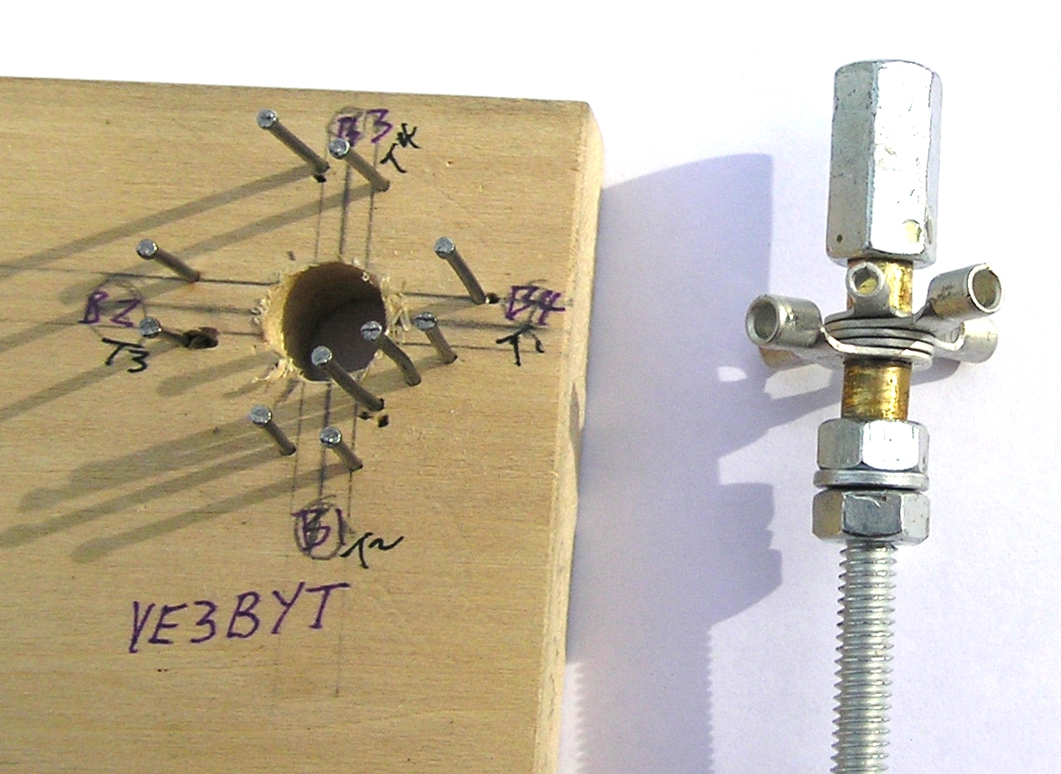
When
the two stacks of lugs are assembled and soldered, place them both on
the steel
rod jig with a metallic spacer between them.
Line up the lugs for the coaxial cable attachment.
If the elements are copper, bronze or brass, they will be
soldered in the lugs while on this jig; if they are aluminum they will
be cleaned and crimped.
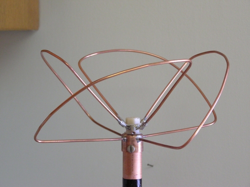
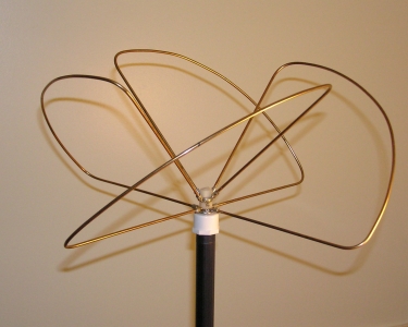
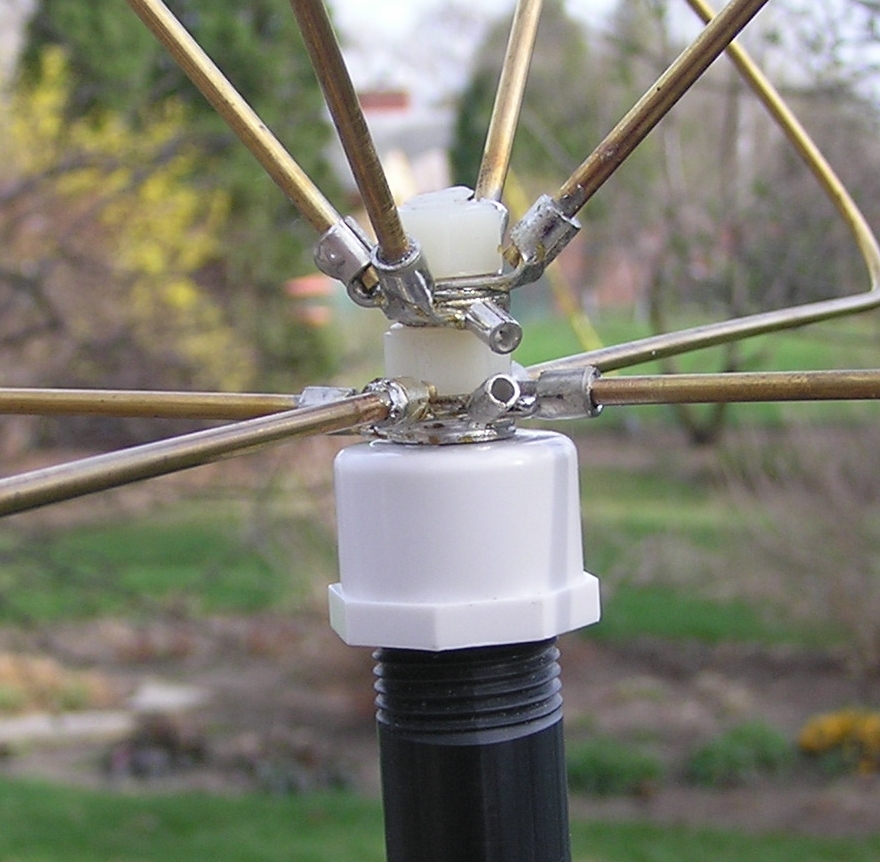
Each element is shaped as shown in Figure 4 and in Photos 1 and 2. On each end of an element at the ¼ length point, make a bend around a fairly short radius – for the 440 MHz antenna this was around a radius of about ½ inch. The half element portion is curved out so that the straight ¼ length sections meet and form an angle with each other of about 100 degrees. If necessary, adjust slightly the curvature where the one-quarter and the half element lengths meet. Referring to Photo 2 and Photo 3, you can see how everything fits together. The elements are assembled on the hub with the long section of each element (the half element length part) at 45 degrees to the horizontal, for right-hand circular polarization slanted up to the right when you are looking at the closest element. The upper end of each element goes into the lug on the top stack at 90 degrees counterclockwise from its lug on the bottom stack. This is easier to accomplish than it is to describe. The coaxial cable should be
attached while the assembly is on the steel rod before transferring it
onto the pipe cap. The coax
centre conductor is soldered to the top stack and the shield to the
bottom. When all the
elements and the coax are soldered to the lug stacks, the assembly
becomes quite manageable and the steel rod can be easily be removed and
replaced by the threaded nylon rod and the plastic spacer, and the whole
thing mounted on the pipe cap. The
antenna is then mounted on its mast pipe.
If you wish, a hole can be made in the mast pipe to pass the
feedline coax through and down inside the pipe. Coat the centre hub ( nylon
rod, spacer and nuts, and the lug stacks), and the feedline connections
with PlastiDip or Liquid Electrical tape to seal against moisture.
Use at least two coats on all of these areas.
If you use copper or bronze for the elements, they should be
sprayed with several coats of the acrylic spray to protect them against
discolouration and corrosion. If
aluminum is used for the elements, the area where they are crimped into
the lugs should be coated with PlastiDip. If the antenna is to be
mounted on a metal mast, it must be at the top, or the antenna can be
offset from a metal mast or tower by about 60 cm (two feet) or more.
Ensure that the coaxial feedline is taken away from the antenna
at a point lower than the antenna elements.
There should not be any metal near the antenna in the plane of
the elements. Following the net, Clare
Fowler, VE3NPC, gave me reports using first his right-hand circularly
polarized helical antenna and then compared my signal as received on a
helix wound for left-hand polarization.
The results showed that this Skew-Planar is strongly right-hand
circularly polarized, as expected.
At my end, Clare's signal was S8 with his right-hand helix, and
dropped to S1 when he switched to his left-hand helix.
This is a remarkable difference in received signal level – much
more than should be expected. This
was probably because my S-meter has not been calibrated (and perhaps it
is trying to make me feel good about the Skew-Planar antenna). This is possibly the first
time that this antenna design has been analysed, constructed and tested
on the air since its introduction in 1963.
It has been found to meet the objectives for an omnidirectional
antenna that can work effectively with both horizontally and vertically
polarized stations. Based on this preliminary testing of the Skew-Planar Wheel, I
am confident that when I switch to more appropriate feedline (Heliax)
and mount the antenna in the clear at its final dizzying height of 10
metres (33 feet), it will meet my expectations for local work with
repeaters and mobiles and with weak-signal stations using horizontal
antennas. The 440 MHz antenna is not
very large in size, so I have begun to build a second one.
They will be stacked one above the other to achieve 3 dB of
additional gain. I will
rebuild the antenna for the 903 MHz beacon.
When I figure out where I could mount it, I may put up a
Skew-Planar Wheel antenna for the 2 Metre band as well.
And there is a possible variation of the design that I want to
investigate with David, VE3KL. Stacking of Two Antennas Two or more of these antennas
can be stacked, but not one above the other on a metal mast.
There must not be metal in the plane of the elements. The optimum stacking distance is 5/8 wavelength for 3 dB of
gain compared to a single antenna.
Stacking for two antennas is done by putting the pipe cap for the
lower antenna on the top of its assembled hub rather than on the bottom. Then the antennas are separated using the correct length of
plastic pipe or other non-conducting material, such as sealed wood.
You could use a pipe 'T' in the middle of this pipe to carry a
horizontal standoff to your tower or mast, or use some other standoff
arrangement. It is also
possible to put an additional pipe cap on the bottom of the lower
antenna and mount the two antennas on their own mast, although this
arrangement may not be sufficiently sturdy to withstand wind and icing
conditions. The two
antennas should be fed with equal lengths of coaxial cable from a
two-port power divider. Again,
the coaxial feedlines must not be in the horizontal plane of the antenna
elements near the antenna. Acknowledgements Table 2 – Materials and Parts 1 Spacer, about 3/8 inch long for 440 MHz – a length of inner insulation from RG-8 coaxial cable, nylon nuts or washers or other low loss plastic - to fit over the threaded rod to separate the upper and lower lug stacks (element attachment assemblies). 2 Nylon nuts to fit the ends of the nylon threaded rod. Brass or steel nuts could be used. 8 Crimp type lugs to fit the #8 wire, tubing or rod elements, with a stud hole to fit your threaded nylon rod. (Lugs sold for #12-10 AWG wire are a nice fit for #8 AWG or 1/8 inch rod) 2 Crimp type lugs for #16-14 AWG with stud hole to fit the threaded nylon rod (attachment points for coaxial cable) Clear acrylic
spray, for exterior use, ultraviolet radiation resistant, such as Krylon
UV-Resistant Clear (available through art-supply stores). References / Links All of the links listed here
are available in active form in Hot Links on the Radio Amateurs of
Canada web site. Go to <http:www.rac.ca>,
then to TCA, then click on Hotlinks. [1]
The Lindenblad Antenna – example for 2 Metres from the
Satellite Experimenter's Handbook <http://www.amsat.org/amsat/articles/w6shp/lindy.html> [2]
The Skew-Planar Wheel Antenna, by Robert H. Mellen, W1IJD, and
Carl T. Milner, W1FVY. QST,
November 1963, page 11. [4]
The Big Wheel on Two, by Robert H Mellen, W1IJD, and Carl T.
Milner, W1FVY. QST,
September 1961, page 42. [5]
EZNEC antenna analysis software authored by Roy Lewallen, W7EL <www.eznec.com/> - 30 -
|
||||||||||||||||||||||||||||||||||||||||||||||||||||||||||||||||||||||||||||||||||||||||||||||||||||||||||||||||